Good Design pays for itself
It happened to us in Fab start-up projects: SHK has been founded with experience in equipment engineering and Hook-Up design. We moved further into facility areas via Industrial Engineering and the design of AMHS and equipment layouts, until we finally designed all elements in the cleanroom and subfab. After this we started to design entire fab buildings. So we basically developed our experience against the flow direction of the facility supply systems (in flow direction of exhaust air and waste water) or from inside to outside.
With this knowledge, we started in some recent fab start-up projects after architects and planners, who tend to think from the direction of facility centrals and from outside to inside, had already finished their design and it was too late to make any changes.
That was sometimes unlucky, because often the building, structural and facility systems specialists have said that a different arrangement of shear walls, a change in room heights, a different positioning of shafts or stairwells would have been no problem if they had known about the need earlier.
A better space management for Hook-Up, different positions of building structural elements for better AMHS routings, or better usable space for placing more equipments, wouldn’t have been a problem, again, if they’d had the information earlier.
“But now everything is finally designed and we are late in schedule so we can’t change it.”
Fabs are being built that, although new, have some rough edges for their entire lifetime. In the end, because there is no direct comparison, it does not become transparent whether perhaps a better Fab could have been built in less time with less budget if it had been better planned through?
The employees always make later the best out of what is there and find creative ways to deal with existing restrictions. Sometimes a gowning room or an office is built out as cleanroom extension or an intermediate building is added…
This result in sites with more and more compromises and restrictions which are at some point very limited for a larger adaptation, e.g. to a new technology or a larger wafer size.
When investments getting higher, good design pays very much for itself. The potential to achieve high space efficiency is particularly high at the start of the design process. Here everything can still be changed and optimized to reach the best possible Fab core design with all Elements well postitioned in the cleanroom and subfab.
It is the same in value engineering. Better thought-out solutions, shorter lines, better interaction between all areas have their highest potential in the first stages of the design process. Not only with the buildings but also with facility and later Hook-Up design, more and more facts are created in the course of the project that can no longer be adjusted without jeopardizing the schedule.
The cornerstones for the schedule are laid early. The type of project process and organization, the sooner or later involvement of specialized consultants, companies and suppliers have a big influence on the project speed. The sizes of the phases for the cleanroom expansion are defined early on. The time to market can be significantly shortened by build out only a first cleanroom section at the beginning but this need to be considered from day one in design.
Finally, many important basics of operation and maintenance costs are defined at the very beginning of the project. Can the energy demand be optimized by short lines and thus lower pressure drops, can the number of lifting stations be reduced by an better placement of waste water treatment, can the emergency egress or access for maintenance be optimized and, and, and. Sustainability can also be improved by reducing the volume of space and thus saving concrete.
All these important decisions are made in the first design phases, in particular in Conceptual Design. At the beginning, the investment is still small and therefore the pressure to achieve the return of investment as quickly as possible is not yet there. In Conceptual Design is room for creative out-of-the-box ideas and research of variants – if started early enough!
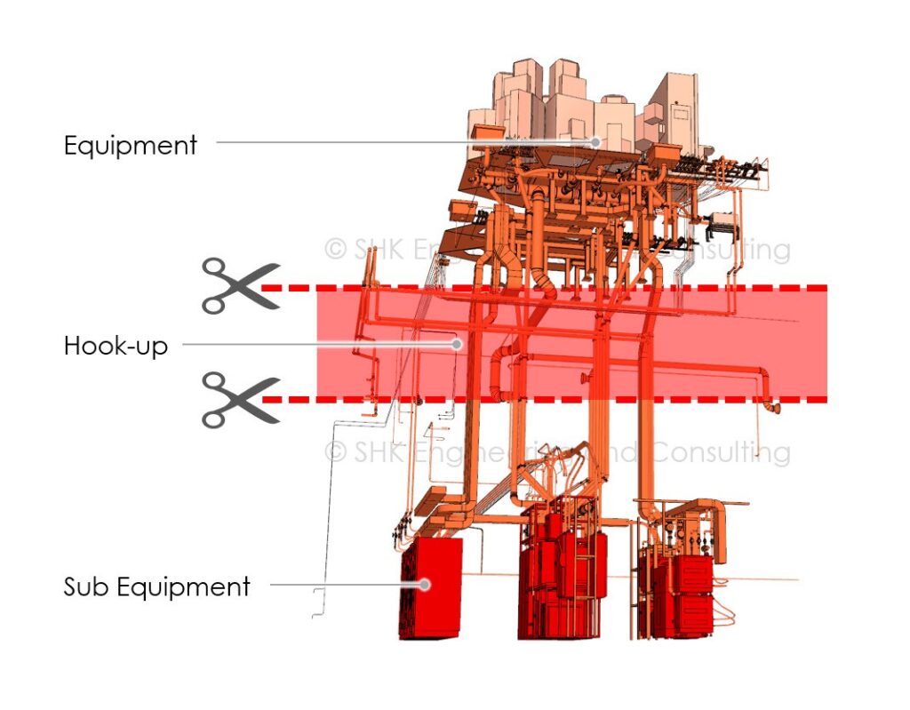
Only if a team of Designers with togehther the full bandwith of knowlede are involved in the first design phases, with experience in the Facility centrals AND the core of the Fab, who have developed Subfab Layouts, designed Process Laterals and Hook-Up, know about Equipment Engineering, went through the development process of AMHS and Equipment layouts and have knowlege in designing Facilty centrals, buildings and site plans, the new Fab will be well thought out.
Conceptual Design for a larger new Fab costs around two million US$, so less than 0.1% of the total investment of a new Fab building. If a Fab designer finds potential of only 1%, not only has the design paid for itself, but there is also a lot left over as savings.
In the aerospace industry, redundant design has long been state of the art. Fab projects are becoming more and more expensive and complex. Isn’t redundant Conceptual Design worth considering as well in our industry?
Comment on LinkedIn
Is there a perfect Fab design?
All modern 300mm front-end fabs are fully automated, have more or less the same functional areas, and are generally built on almost flat sites. All fabs have a cleanroom with similar temperature and humidity specs, a Subfab and need basically identical facility systems.
The picture above shows one cube each from the core of the fab building of 5 different existing Fabs. Almost no dimensions are the same. The heights of the waffleslab above ground level are very different, the grid spacing is different, raised floor or cleanroom heights are from low to high, and many, many very fundamental further differences not shown, such as the arrangement of the process laterals, the hook-up space management, the location of the facility centrals.
It is interesting to note that in our experience, fab buildings in Taiwan are much more similar to each other than they are in other countries.

Are the differences perhaps just because the best form factor for Fabs has not yet been found? After all, it took many iterations to find the perfect form factor for cell phones. Modern smartphones no longer differ so fundamentally in their dimensions and also in the layout of the internal components. It is interesting that also here the functions have become much more complex and extensive in the past decades and the inner structure has been condensed very much at the same time. Every inch³/mm³ of space is fought for here.
Shouldn’t we also fight for every ft³/m³ of space in Fab design? Reasonably compact buildings have great advantages because they require less of everything that makes a Fab project so expensive and complex to build.
If you take a closer look at the height between the Subfab and the raised floor, for example, there are deltas of up to almost 12 feet or over 3 ½ m.
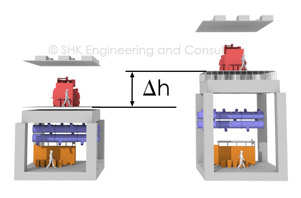
If one imagines a disk of this thickness on the plane with the most vertical installations in a fab, it would have a considerable value.
Modern 3D design is one key to more compact results. This is not only true for smartphones but also for many other things that have evolved so much.
Another key is a very deep understanding of precise actual and future equipment demands. Looking back and using rough benchmark numbers will not be enough to design a modern compact Fab for future demands.
The SHK software SemiSoft® is designed to capture and manage all data relevant to the building and facility infrastructure. The 3D tools are so easy to use that they motivate to explore variations and work on them until the best solution is found. The DataCube© technology visualize the detailed Facility Utility Matrix on various hierarchies.
SemiSoft® is very useful for our current internal Fab Design R&D project. We are taking the time to examine the aspects of a perfect Fab building and try to assemble a virtual new Fab model from the results. In any case: this is fun and we learn a lot.
Comment on LinkedIn
The level of detail should fit the task
When it comes to modern engineering and design, the buzzwords 3D and BIM are a “must”. What exactly stands behind these terms, however, is sometimes interpreted differently. A solid that looks like a pipe but has no references to material and technical data should not be called BIM and neither 3D pipework design.
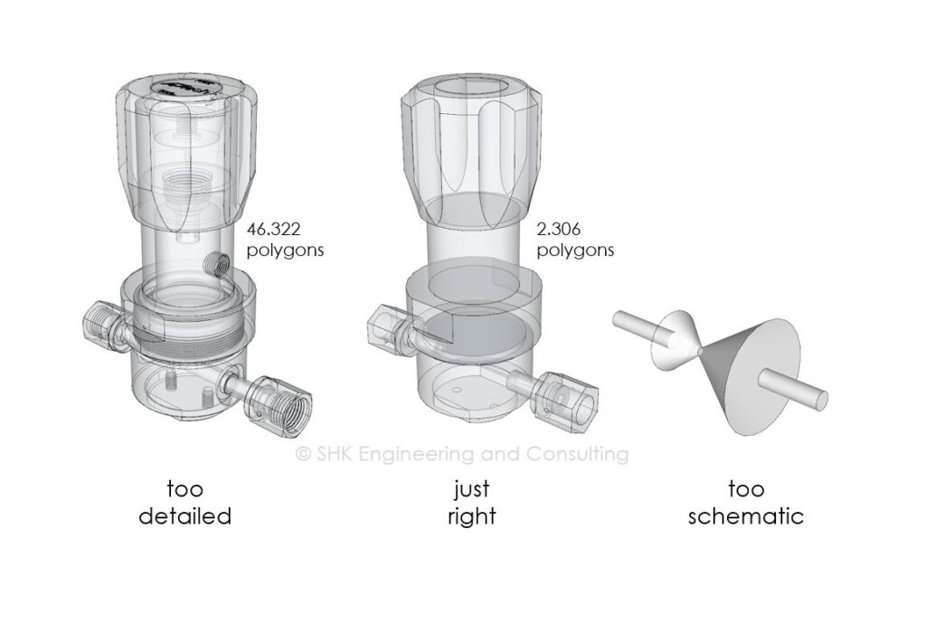
We at SHK started many years ago with 3D design and begun soon to assign data to our 3D models, long before the term BIM became better known. Before adding data and work with data 3D models must have a certain degree of detail in order to provide value with the deliverables to the construction management.
Schematic 3D design can look quite nice at a first sight but when it comes to installation it does not really help if dimension of components in reality are different to dimensions in the conceptual 3D model or other installation critical dimensions are not considered. This could result easily into construction problems where installations are not possible as designed.
Would it then not be the best solution just to download 3D models from the component manufacturers websites? Unfortunately not, as in most cases the component manufacturer models are generated for a different purpose and are therefore much too detailed for Fab design demands. Just a few of these components could slow down the design process to the point where creative and efficient work is no longer possible.
It was not an easy walk on a beaten track but today we can say with certainty that it was the right way: At SHK, we have modeled every single component in our 3D libraries from scratch. We make them to real digital twins with our patented DataCube© technology with BIM data embedded inside the components.
SHK own today libraries with ten-thousands of own 3D components with DataCubes©, aligned to the needs of the Fab design and construction industry. These BIM libraries are one of the reasons why SHK can generate such well thought out deliverables with a small team in a short period of time.
Comment on LinkedIn
Different values of cleanrooms
The capacity of a Fab is directly related to the cleanroom size. But not only the area matters, also the type of cleanroom result in relevant space efficiency differences.
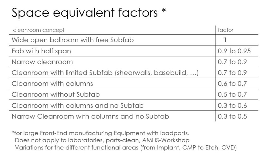
See above, what happen if you look closer on a dry-etch space with about 5500 ft²/500 m². In this area 19 larger chamber equipments can be placed well in a ballroom with free Subfab.
The same cleanroom size, but with columns every 24’/7,2m, the situation is very different. Two of these typical etch equipments do not fit between the columns, so only one equipment between two columns can be placed. This result in space for only 12 equipments or an space efficiency of only 60% in comparison to the ballroom.
Without Subfab and with columns, the area efficiency, in the same cleanroom size, goes down to only 30% as Sub Equipment need to be installed on the cleanroom level.
SHK reviewed different cleanroom concepts regarding space efficiency of various projects we have been involved. There are quite a number of more space restrictions for 300mm Fab cleanrooms beside the topics mentioned above: In narrow buildings the efficiency goes down due to the higher ratio of move-in aisles/equipment areas. Columns result also in constraints for a clear and straight AMHS layout. Facility installations in the Subfab limit in consequence usable equipment space. And some more. One result of our Fab design research project are conceptual design factors for the different cleanroom types.
Imagine you could build a Fab smaller because the clean room can be used only some percent more efficiently. With the high investments in building and infrastructure this could easily result in remarkable savings – up to the value of an EUV cluster. Or the other way around: More high value manufacturing space for the same money would be an even better benefit for a new Fab project.
Unfortunately, to realize high space efficiency, knowledge alone is not enough. Without continuous follow up throughout the entire design and construction phase many not-equipment-related installations will grow into manufacturing space before the first equipment arrives.
In any case: The one who consider cleanroom efficiency in conceptual fab design will be in the lead and the more Giga, the easier it will be to achieve high space efficiency.
Comment on LinkedIn
How big is Giga?
the illustration above show two site plots with manufacturing and support buildings with approximate external dimensions and in the same scale.
The Fab on the left side was recently opened with buildings for Cleanroom 1. The builder says that this is the largest single investment in the history of their company. The right Fab is in operation with Cleanroom 1 and the buildings for Cleanroom 2 are currently under construction.
Some numbers:
- Site plot: 17 times bigger
- Cleanroom: 14 times bigger in full buildout
- Investment: 1.2 bill. US$ (left with cleanroom 1) vs. 24 bill. US$ (right, full expansion)
Some thousand square meter cleanroom are not small. 70,000m² cleanroom is Giga, especial if as ballroom and with full subfab!
Fab sizes according TSMC: Mini ~10k, Mega ~25k and Giga >100k wspm. TSMC Fabs 12, 14 and 15 are Gigafabs, Samsung, YMTC, SK Hynix, SMIC, Nexchip, GF and Intel are also on the Gigapath.
Economy of scale is getting an more and more important key element for successful semiconductor production. The Gigarace is in full swing. Leaders are fast and clearly in front.
It can be assumed that Fabs have to get that big to be competitive, and this for an continuous growing bandwidth of products
So what are the most important success factors in the chip race? Process technology, time to market, yield, less expensive Fabs, deep pockets or all together?
Some Aerial views show the extend of different site plots. (copy the link into your browser to explore the sites)
TSMC, Taiwan
https://fatmap.com/waypoint//_Taiwan//@24.2089905,120.6075925,5000
YMTC, China
https://fatmap.com/waypoint//Hubei_China//@30.4647292,114.5980535,5000
Nexchip, China
https://fatmap.com/waypoint//Anhui_China//@31.9509113,117.3462313,5000
Samsung, South Korea
https://fatmap.com/waypoint//_S%C3%BCdkorea//@37.0337006,127.0599505,5000
SK Hynix, South Korea
https://earth.google.com/web/search/sk+hynix/@37.24922571,127.48684601,88.38073117a,2111.07063424d
Globalfoundries, USA
https://fatmap.com/waypoint//New_York_Vereinigte_Staaten_von_Amerika//@42.9694048,-73.7539923,5000
Comment on LinkedIn
Three topics, one solution
First topic: Gas detection limitations because of dilution with exhaust air
Gas detectors connected to equipment gas boxes are limited in their detection reliability due to the fact that the high extracted exhaust volume dilutes leaks by a factor of some hundred times or more.
An example from one of our projects: A leak in the gasbox from a doped-poly furnace, caused by a loosened VCR connection, was not detected. We reconstructed the event and fed calibration gas into the gas box after calibrating the gas detector and checking its operation. It was confirmed what we had already expected: Even a medium leak could not be detected by the gas detector, because the dilution in the exhaust air reduced the proportion of the gas to be detected below the detection limit of the sensor.
It is a known problem: Reducing the exhaust air flow increases the detection sensitivity but at the same time it reduces the safety in case of a larger leak.
Second topic: Space management issues because of large exhaust pipes
A large part of the building volume or building height is needed due to the large diameters of exhaust piping systems. Any reduction of exhaust piping diameters would help the space management and could even allow to reduce the building volume and height.
Third topic: All exhausted air must be replaced with make-up air
In order to maintain the positive pressure in the clean room, each cubic meter of extracted exhaust air must be replaced by an costly processed cubic meter of fresh air. Make up air units are expensive, have high operation costs and need a lot of space. Reducing the size of these units would result in measurable savings.
One solution

SHK has developed a patented unit as solution for all three topics. The unit is installed in the hook-up line of the gas box. A safety magnet, similar to those used to hold fire doors, holds the exhaust damper in a more closed position. The small exhaust volume allows to detect even very small leaks. As soon as a leakage is detected, the magnet is released and the spring opens the damper completely.
This unit introduced in all exhaust lines from gasboxes and valve manifold boxes will increase safety. As the overall exhaust volume is reduced, exhaust pipes and make up air handling units can be sized smaller at the same time. The resulting savings make sure that the system pays off within a short period of time.
450mm ready
Fab buildings are getting more and more expensive. The lifespan of these valuable properties are measured in decades rather than years.
Increasing wafer sizes has long been an essential tool for increasing a Fab’s manufacturing efficiency. Yield, shrink and manufacturing efficiency were always further measures.
The time will come when the biggest potential in increasing manufacturing efficiency is once again increasing the wafer size. That time will very definitely be within the lifetime of many fabs being designed or built today.
Even if it still sounds very much like the future, modern fab buildings should be “450mm ready”.
Comment on LinkedIn